Wednesday 23 May 2012
Tuesday 22 May 2012
types of engine
 |
4 types of engine |
 |
4 cylinder i type |
 |
radial 5 cylinder |
 |
types of engine |
 |
parts of engine |
 |
inline 4 cylinder engine |
 |
opposed(flat)engine |
 |
opposed engine |
 |
radial engine |
 |
radial engine 7 cylinder |
 |
rotary engine |
 |
rotary engine |
 |
rotary engine 3D |
 |
v type engine |
 |
w type 12 cylinder engine |
Internal Combustion Engine

Internal combustion engines are one of the
building blocks of modern civilization. In an internal combustion
engine, the combustion takes place inside a confined chamber. All
internal combustion engines burn a mixture of air & fuel. The fuel
can be gasoline, diesel, methane, propane etc.
The piston is the heart of an internal combustion
engine..The concept of the piston engine is that a supply of
air-and-fuel mixture is fed to the inside of the cylinder where it is
compressed and then burnt. This internal combustion releases heat energy
which is then converted into useful mechanical work as the high gas
pressures generated force the piston to move along its stroke in the
cylinder. It can be said, therefore, that a heat-engine is merely an
energy transformer.
To enable the piston movement to be harnessed,
the driving thrust on the piston is transmitted by means of a
connecting-rod to a crankshaft whose function is to convert the linear
piston motion in the cylinder to a rotary crankshaft movement (Fig.
1.1-1). The piston can thus be made to repeat its movement to and fro,
due to the constraints of the crankshaft crankpin’s circular path and
the guiding cylinder.
The backward-and-forward displacement of the
piston is generally referred to as the reciprocating motion of the
piston, so these power units are also known as reciprocating engines.

 Animation of two-stroke engine in operation, with a tuned pipe exhaust
 An automobile engine partly opened and colored to show components.
The internal combustion engine is an engine in which the combustion of a fuel (normally a fossil fuel) occurs with an oxidizer (usually air) in a combustion chamber. In an internal combustion engine, the expansion of the high-temperature and high -pressure gases produced by combustion apply direct force to some component of the engine. This force is applied typically to pistons, turbine blades, or a nozzle. This force moves the component over a distance, transforming chemical energy into useful mechanical energy. The first functioning internal combustion engine was created by Étienne Lenoir.[1]
An automobile engine partly opened and colored to show components.
The internal combustion engine is an engine in which the combustion of a fuel (normally a fossil fuel) occurs with an oxidizer (usually air) in a combustion chamber. In an internal combustion engine, the expansion of the high-temperature and high -pressure gases produced by combustion apply direct force to some component of the engine. This force is applied typically to pistons, turbine blades, or a nozzle. This force moves the component over a distance, transforming chemical energy into useful mechanical energy. The first functioning internal combustion engine was created by Étienne Lenoir.[1]
The term internal combustion engine usually refers to an engine in which combustion is intermittent, such as the more familiar four-stroke and two-stroke piston engines, along with variants, such as the six-stroke piston engine and the Wankel rotary engine. A second class of internal combustion engines use continuous combustion: gas turbines, jet engines and most rocket engines, each of which are internal combustion engines on the same principle as previously described.[1]
The internal combustion engine (or ICE) is quite different from external combustion engines, such as steam or Stirling engines, in which the energy is delivered to a working fluid not consisting of, mixed with, or contaminated by combustion products. Working fluids can be air, hot water, pressurized water or even liquid sodium, heated in some kind of boiler.
A large number of different designs for ICEs have been developed and built, with a variety of different strengths and weaknesses. Powered by an energy-dense fuel (which is very frequently gasoline, a liquid derived from fossil fuels). While there have been and still are many stationary applications, the real strength of internal combustion engines is in mobile applications and they dominate as a power supply for cars, aircraft, and boats.
another defination

The term internal combustion engine usually refers to an engine in which combustion is intermittent, such as the more familiar four-stroke and two-stroke piston engines, along with variants, such as the six-stroke piston engine and the Wankel rotary engine. A second class of internal combustion engines use continuous combustion: gas turbines, jet engines and most rocket engines, each of which are internal combustion engines on the same principle as previously described.[1]
The internal combustion engine (or ICE) is quite different from external combustion engines, such as steam or Stirling engines, in which the energy is delivered to a working fluid not consisting of, mixed with, or contaminated by combustion products. Working fluids can be air, hot water, pressurized water or even liquid sodium, heated in some kind of boiler.
A large number of different designs for ICEs have been developed and built, with a variety of different strengths and weaknesses. Powered by an energy-dense fuel (which is very frequently gasoline, a liquid derived from fossil fuels). While there have been and still are many stationary applications, the real strength of internal combustion engines is in mobile applications and they dominate as a power supply for cars, aircraft, and boats.
Comparison of SI and CI Engine
Comparison of SI and CI Engine
Comparison of S.I. and C.I. engines is made from various aspects is made below:
Fuel economy
The chief
comparison to be made between the two types of engine is how effectively
each engine can convert the liquid fuel into work energy. Different
engines are compared by their thermal efficiencies. Thermal efficiency
is the ratio of the useful work produced to the total energy supplied.
Petrol engines can have thermal efficiencies ranging between 20% and
30%. The corresponding diesel engines generally have improved
efficiencies, between 30% and 40%. Both sets of efficiency values are
considerably influenced by the chosen compression-ratio and design.
Power and torque
The
petrol engine is usually designed with a shorter stroke and operates
over a much larger crankshaft-speed range than the diesel engine. This
enables more power to be developed towards the upper speed range in the
petrol engine, which is necessary for high road speeds; however, a
long-stroke diesel engine has improved pulling torque over a relatively
narrow speed range, this being essential for the haulage of heavy
commercial vehicles.
At the time of writing, there was a trend to
incorporate diesel engines into cars. This new generation of engines has
different design parameters and therefore does not conform to the above
observations.
Reliability
Due to
their particular process of combustion, diesel engines are built
sturdier, tend to run cooler, and have only half the speed range of most
petrol engines. These factors make the diesel engine more reliable and
considerably extend engine life relative to the petrol engine.
Pollution
Diesel
engines tend to become noisy and to vibrate on their mountings as the
operating load is reduced. The combustion process is quieter in the
petrol engine and it runs smoother than the diesel engine. There is no
noisy injection equipment used on the petrol engine, unlike that
necessary on the diesel engine.
The products of combustion coming out of the exhaust system are
more noticeable with diesel engines, particularly if any of the
injection equipment components are out of tune. It is questionable which
are the more harmful: the relatively invisible exhaust gases from the
petrol engine, which include nitrogen dioxide, or the visible smoky
diesel exhaust gases.
Safety
Unlike petrol,
diesel fuels are not flammable at normal operating temperature, so they
are not a handling hazard and fire risks due to accidents are minimized.
Cost
Due to their heavy construction and injection equipment, diesel engines are more expensive than petrol engines.
Difference b/w 2 & 4 stroke petrol engine
Difference Between Two & Four Stroke Cycle Petrol Engines
The differences between two- and
four-stroke-cycle petrol engines regarding the effectiveness of both
engine cycles are given below:
a) The two-stroke engine
completes one cycle of events for every revolution of the crankshaft,
compared with the two revolutions required for the four-stroke engine
cycle.
b) Theoretically, the two-stroke
engine should develop twice the power compared to a four-stroke engine
of the same cylinder capacity.
c) In practice, the two-stroke
engine's expelling of the exhaust gases and filling of the cylinder with
fresh mixture brought in through the crankcase is far less effective
than having separate exhaust and induction strokes. Thus the mean
effective cylinder pressures in two-stroke units are far lower than in
equivalent four-stroke engines.
d) With a power stroke every
revolution instead of every second revolution, the two-stroke engine
will run smoother than the four-stroke power unit for the same size of
flywheel.
e) Unlike the four-stroke
engine, the two-stroke engine does not have the luxury of separate
exhaust and induction strokes to cool both the cylinder and the piston
between power strokes. There is therefore a tendency for the piston and
small-end to overheat under heavy driving conditions.
f) Due to its inferior scavenging process, the two-stroke engine can suffer from the following:
i) inadequate transfer of fresh mixture into the cylinder,
ii) excessively large amounts of residual exhaust gas remaining in the cylinder,
iii) direct expulsion of fresh charge
through the exhaust port.
These undesirable conditions may occur under different speed and
load situations, which greatly influences both power and fuel
consumption.
g) Far less maintenance is
expected with the two-stroke engine compared with the four-stroke
engine, but there can be a problem with the products of combustion
carburizing at the inlet, transfer, and exhaust ports.
h) Lubrication of the two-stroke
engine is achieved by mixing small quantities of oil with petrol in
proportions anywhere between 1:16 and 1:24 so that, when crankcase
induction takes place, the various rotating and reciprocating components
will be lubricated by a petrol-mixture mist. Clearly a continuous
proportion of oil will be burnt in the cylinder and expelled into the
atmosphere to add to unwanted exhaust emission.
i) There are fewer working parts
in a two-stroke engine than in a four-stroke engine, so two-stroke
engines are generally cheaper to manufacture.
valve timing diagram
Valve timing diagram of a four stroke engine
gives a clear idea about the actual position of the piston during the
opening & closing of inlet & exhaust valves. In practice, the
events of the four-stroke cycle do not start and finish exactly at the
two ends of the strokes - to improve the breathing and exhausting, the
inlet valve is arranged to open before TDC and to close after BDC and
the exhaust valve opens before BDC and closes after TDC. These early and
late opening and closing events can be shown on a valve timing diagram
such as Fig. 1.1-4.

Valve lead This is where a valve opens so many degrees of crankshaft rotation before either TDC or BDC.
Valve lag This is where a valve closes so many degrees of crankshaft rotation after TDC or BDC.
Valve overlap This is
the condition when both the inlet and the exhaust valves are open at the
same time during so many degrees of crankshaft rotation.
compression ratio
Compression-ratio is a very important parameter
for measuring engine performance.The compression-ratio may be defined as
the ratio of the maximum cylinder volume when the piston is at its
outermost position (BDC) to the minimum cylinder volume (the clearance
volume) with the piston at its innermost position (TDC) - that is, the
sum of the swept and clearance volumes divided by the clearance volume,
Vs þVc i:e: CR ¼ Vc
where CR ¼ compression ratio
Vs ¼ swept volume (cm3) Vc ¼ clearance volume (cm3)
Petrol engines have compression-ratios of the
order of 7:1 to 10:1; but, to produce self-ignition of the charge,
diesel engines usually double these figures and may have values of
between 14:1 and 24:1 for naturally aspirated (depression-induced
filling) types, depending on the design.
In an engine cylinder, the gas molecules are
moving about at considerable speed in the space occupied by the gas,
colliding with other molecules and the boundary surfaces of the cylinder
head, the cylinder walls, and the piston crown. The rapid succession of
impacts of many millions of molecules on the boundary walls produces a
steady continuous force per unit surface which is known as pressure
(Fig. 1.1-12).

When the gas is compressed into a much smaller
space, the molecules are brought closer to one another. This raises the
temperature and greatly increases the speed of the molecules and hence
their kinetic energy, so more violent impulses will impinge on the
piston crown. This increased activity of the molecules is experienced as
increased opposition to movement of the piston towards the cylinder
head.
The process of compressing a constant mass of gas
into a much smaller space enables many more molecules to impinge per
unit area on to the piston. When burning of the gas occurs, the chemical
energy of combustion is rapidly transformed into heat energy which
considerably increases the kinetic energy of the closely packed gas
molecules. Therefore the extremely large number of molecules squeezed
together will thus bombard the piston crown at much higher speeds. This
then means that a very large number of repeated blows of considerable
magnitude will strike the piston and so push it towards ODC.
This description of compression, burning, and
expansion of the gas charge shows the importance of utilising a high
degree of compression before burning takes place, to improve the
efficiency of combustion. The amount of compression employed in the
cylinder is measured by the reduction in volume when the piston moves
from BDC to TDC, the actual proportional change in volume being
expressed as the compression-ratio.
MAJOR engine components
Identification of major engine components makes
it easier to understand its working principle. Some major engine
components are, cylinder block, piston, piston rings, connecting-rod,
cylinder head, crankcase, crankshaft etc. The following briefly
describes the major engine components and some terms associated with
them.
Cylinder block
This is a cast structure with cylindrical holes bored to guide and
support the pistons and to harness the working gases. It also provides a
jacket to contain a liquid coolant.
Cylinder head
This
casting encloses the combustion end of the cylinder block and houses
both the inlet and exhaust poppet-valves and their ports to admit air-
fuel mixture and to exhaust the combustion products.
Crankcase
This is a
cast rigid structure which supports and houses the crankshaft and
bearings. It is usually cast as a mono-construction with the cylinder
block.
Sump
This is a
pressed-steel or cast-aluminum-alloy container which encloses the bottom
of the crank-case and provides a reservoir for the engine's lubricant.

Piston
This is a
pressure-tight cylindrical plunger which is subjected to the expanding
gas pressure. Its function is to convert the gas pressure from
combustion into a concentrated driving thrust along the connecting-rod.
It must therefore also act as a guide for the small-end of the
connecting-rod.
Piston rings
These are
circular rings which seal the gaps made between the piston and the
cylinder, their object being to prevent gas escaping and to control the
amount of lubricant which is allowed to reach the top of the cylinder.
Gudgeon-pin
This pin
transfers the thrust from the piston to the connecting-rod small-end
while permitting the rod to rock to and fro as the crankshaft rotates.
Connecting-rod
This acts as
both a strut and a tie link-rod. It transmits the linear pressure
impulses acting on the piston to the crankshaft big-end journal, where
they are converted into turning-effort.
Crankshaft
A simple
crankshaft consists of a circular-sectioned shaft which is bent or
cranked to form two perpendicular crank-arms and an offset big-end
journal. The unbent part of the shaft provides the main journals. The
crankshaft is indirectly linked by the connecting-rod to the piston -
this enables the straight-line motion of the piston to be transformed
into a rotary motion at the crankshaft about the main-journal axis.
Crankshaft journals
These
are highly finished cylindrical pins machined parallel on both the
centre axes and the offset axes of the crankshaft. When assembled, these
journals rotate in plain bush-type bearings mounted in the crankcase
(the main journals) and in one end of the connecting-rod (the big-end
journal).
Small-end
This refers to
the hinged joint made by the gudgeon-pin between the piston and the
connecting-rod so that the connecting-rod is free to oscillate relative
to the cylinder axis as it moves to and fro in the cylinder.
Big-end
This refers to the
joint between the connecting-rod and the crankshaft big-end journal
which provides the relative angular movement between the two components
as the engine rotates.
Main-ends
This refers to
the rubbing pairs formed between the crankshaft main journals and their
respective plain bearings mounted in the crankcase.
Line of stroke
The centre path the piston is forced to follow due to the constraints of the cylinder is known as the line of stroke.
Inner and outer dead centers
When the crank arm and the connecting-rod are aligned along the line of
stroke, the piston will be in either one of its two extreme positions.
If the piston is at its closest position to the cylinder head, the crank
and piston are said to be at inner dead centre (IDC) or top dead centre
(TDC). With the piston at its furthest position from the cylinder head,
the crank and piston are said to be at outer dead centre (ODC) or
bottom dead centre (BDC). These reference points are of considerable
importance for valve-to-crankshaft timing and for either ignition or
injection settings.
Clearance volume
The space
between the cylinder head and the piston crown at TDC is known as the
clearance volume or the combustion-chamber space.
Crank-throw
The distance
from the centre of the crankshaft main journal to the centre of the
big-end journal is known as the crank-throw. This radial length
influences the leverage the gas pressure acting on the piston can apply
in rotating the crankshaft.
Piston stroke
The piston
movement from IDC to ODC is known as the piston stroke and corresponds
to the crankshaft rotating half a revolution or 180°. It is also equal
to twice the crank-throw.
i.e. L = 2R
where L = piston stroke
and R = crank-throw
Thus a long or short stroke will enable a large or small turning-effort to be applied to the crankshaft respectively.
Cylinder bore
The cylinder
block is initially cast with sand cores occupying the cylinder spaces.
After the sand cores have been removed, the rough holes are machined
with a single-point cutting tool attached radially at the end of a
rotating bar. The removal of the unwanted metal in the hole is commonly
known as boring the cylinder to size. Thus the finished cylindrical hole
is known as the cylinder bore, and its internal diameter simply as the
bore or bore size.
4 stroke cycle petrol engine
FOUR STROKE CYCLE S.I.(Spark ignition)/PETROL ENGINE. 
Gasoline or petrol engines are also known as spark-ignition (S.I.) engines. Petrol engines take in a flammable mixture of air and petrol which is ignited by a timed spark when the charge is compressed. The first four stroke spark-ignition (S.I.) engine was built in 1876 by Nicolaus August Otto, a self-taught German engineer at the Gas-motoreufabrik Deutz factory near Cologne, for many years the largest manufacturer of internal-combustion engines in the world. It was one of Otto's associates - Gottlieb Daimler - who later developed an engine to run on petrol which was described in patent number 4315 of 1885. He also pioneered its application to the motor vehicle.
Four stroke Spark-ignition (S.I) engines require four
piston strokes to complete one cycle: an air-and-fuel intake stroke
moving outward from the cylinder head, an inward movement towards the
cylinder head compressing the charge, an outward power stroke, and an
inward exhaust stroke.
Induction stroke.
The inlet valve is opened and the exhaust valve is closed. The
piston descends, moving away from the cylinder head .
The speed of the piston moving along the cylinder creates a pressure
reduction or depression which reaches a maximum of about 0.3 bar below
atmospheric pressure at one-third from the beginning of the stroke. The
depression actually generated will depend on the speed and load
experienced by the engine, but a typical average value might be 0.12 bar
below atmospheric pressure. This depression induces (sucks in) a fresh
charge of air and atomized petrol in proportions ranging from 10 to 17
parts of air to one part of petrol by weight.
An engine which induces fresh charge by means of a
depression in the cylinder is said to be 'normally aspirated' or
'naturally aspirated'.
Compression stroke.
Both the inlet and the exhaust valves are closed. The
piston begins to ascend towards the cylinder head . The
induced air-and-petrol charge is progressively compressed to something
of the order of one-eighth to one-tenth of the cylinder's original
volume at the piston's innermost position. This compression squeezes the
air and atomized-petrol molecules closer together and not only
increases the charge pressure in the cylinder but also raises the
temperature. Typical maximum cylinder compression pressures will range
between 8 and 14 bar with the throttle open and the engine running under
load.
Power stroke.
Both the inlet and the exhaust valves are closed and, just
before the piston approaches the top of its stroke during compression, a
spark-plug ignites the dense combustible charge. By the
time the piston reaches the innermost point of its stroke, the charge
mixture begins to burn, generates heat, and rapidly raises the pressure
in the cylinder until the gas forces exceed the resisting load. The
burning gases then expand and so change the piston's direction of motion
and push it to its outermost position. The cylinder pressure then drops
from a peak value of about 60 bar under full load down to maybe 4 bar
near the outermost movement of the piston.
Exhaust stroke.
At the end of the power stroke the inlet valve remains closed
but the exhaust valve is opened. The piston changes its direction of
motion and now moves from the outermost to the innermost position. Most of the burnt gases will be expelled by the existing
pressure energy of the gas, but the returning piston will push the last
of the spent gases out of the cylinder through the exhaust-valve port
and to the atmosphere.
During the exhaust stroke, the gas pressure in the cylinder will
fall from the exhaust-valve opening pressure (which may vary from 2 to 5
bar, depending on the engine speed and the throttle-opening position)
to atmospheric pressure or even less as the piston nears the innermost
position towards the cylinder head.
4 stroke cycle diesel engine
FOUR STROKE CYCLE COMPRESSION IGNITION (DIESEL) ENGINE.
Compression-ignition (C.I) engines burn fuel oil which
is injected into the combustion chamber when the air charge is fully
compressed. Burning occurs when the compression temperature of the air
is high enough to spontaneously ignite the finely atomized liquid fuel.
In other words, burning is initiated by the self-generated heat of
compression (Fig. 1.1-8). Compression-ignition (C.I) engines are also
referred to as 'oil engines', due to the class of fuel burnt, or as
'diesel engines' after Rudolf Diesel, one of the many inventors and
pioneers of the early C.I. engine. Note: in the United Kingdom fuel oil
is known as 'DERV', which is the abbreviation of 'diesel-engine road
vehicle'.
Just like the four-stroke-cycle petrol engine,
the Compression-ignition (C.I.) engine completes one cycle of events in
two crankshaft revolutions or four piston strokes. The four phases of
these strokes are (i) induction of fresh air, (ii) compression and
heating of this air, (iii) injection of fuel and its burning and
expansion, and (iv) expulsion of the products of combustion.

Induction stroke.
With the inlet valve open and the exhaust valve closed, the piston moves away from the cylinder head.The outward movement of the piston will establish a depression in the cylinder, its magnitude depending on the ratio of the cross-sectional areas of the cylinder and the inlet port and on the speed at which the piston is moving. The pressure difference established between the inside and outside of the cylinder will induce air at atmospheric pressure to enter and fill up the cylinder. Unlike the petrol engine, which requires a charge of air-and-petrol mixture to be drawn past a throttle valve, in the diesel-engine inlet system no restriction is necessary and only pure air is induced into the cylinder. A maximum depression of maybe 0.15 bar below atmospheric pressure will occur at about one-third of the distance along the piston's outward stroke, while the overall average pressure in the cylinder might be 0.1 bar or even less.Compression stroke.
With both the inlet and the exhaust valves closed, the piston
moves towards the cylinder head.
The air enclosed in the cylinder will be
compressed into a much smaller space of anything from 1/12 to 1/24 of
its original volume. A typical ratio of maximum to minimum air-charge
volume in the cylinder would be 16:1, but this largely depends on engine
size and designed speed range.
During the compression stroke, the air charge
initially at atmospheric pressure and temperature is reduced in volume
until the cylinder pressure is raised to between 30 and 50 bar. This
compression of the air generates heat which will increase the charge
temperature to at least 600 °C under normal running conditions.
Power stroke.
With both the inlet and the exhaust valves closed and the
piston almost at the end of the compression stroke (Fig. 1.1 -8(c)),
diesel fuel oil is injected into the dense and heated air as a
high-pressure spray of fine particles. Provided that they are properly
atomized and distributed throughout the air charge, the heat of
compression will then quickly vaporize and ignite the tiny droplets of
liquid fuel. Within a very short time, the piston will have reached its
innermost position and extensive burning then releases heat energy which
is rapidly converted into pressure energy. Expansion then follows,
pushing the piston away from the cylinder head, and the linear thrust
acting on the piston end of the connecting-rod will then be changed to
rotary movement of the crankshaft.
Exhaust stroke.
When the
burning of the charge is near completion and the piston has reached the
outermost position, the exhaust valve is opened. The piston then
reverses its direction of motion and moves towards the cylinder head.
The sudden opening of the exhaust valve towards
the end of the power stroke will release the still burning products of
combustion to the atmosphere. The pressure energy of the gases at this
point will accelerate their expulsion from the cylinder, and only
towards the end of
the piston's return stroke will the piston actually catch up with
the tail-end of the outgoing gases.
2 stroke cycle diesel engine

.
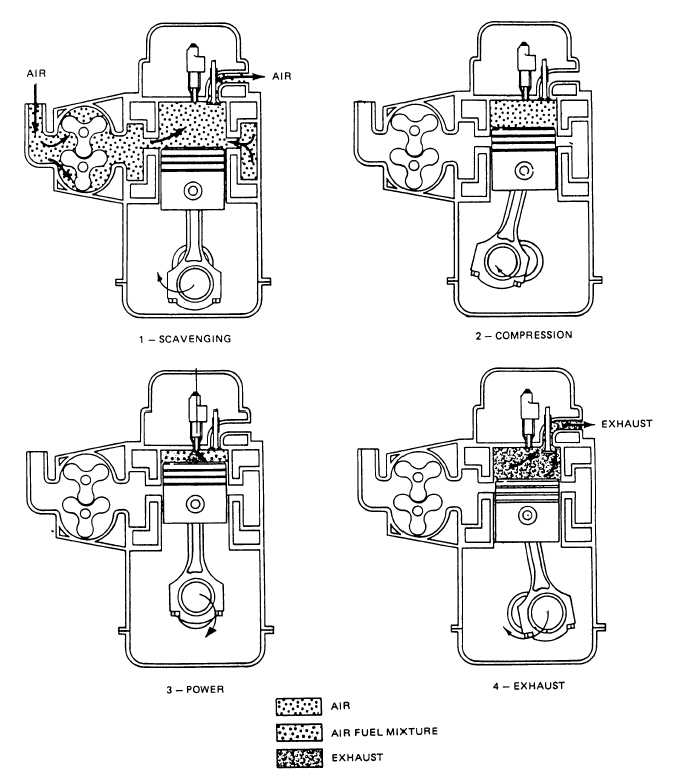
Two-Stroke Cycle Diesel Engine
A two-stroke diesel engine shares the
same operating principles as other internal combustion
engines. It has all of the advantages that other diesel
engines have over gasoline engines.
A two-stroke diesel engine does not produce as
much power as a four-stroke diesel engine; however, it
runs smoother than the four-stroke diesel. This is
because it generates a power stroke each time the piston
moves downward; that is, once for each crankshaft
revolution. The two-stroke diesel engine has a less
complicated valve train because it does not use intake
valves. Instead, it requires a supercharger to force air
into the cylinder and force exhaust gases out, because
the piston cannot do this naturally as in four-stroke
engines.
The two-stroke diesel takes in air and discharges
exhaust through a system called scavenging.
Scavenging begins with the piston at bottom dead
center. At this point, the intake ports are uncovered in
the cylinder wall and the exhaust valve is open. The
supercharger forces air into the cylinder, and, as the air
is forced in, the burned gases from the previous
operating cycle are forced out.
COMPRESSION STROKE.— As the piston
moves towards top dead center, it covers the intake
ports. The exhaust valves close at this point and seals
the upper cylinder. As the piston continues upward, the
air in the cylinder is tightly compressed . As
in the four-stroke cycle diesel, a tremendous amount of
heat is generated by the compression.
POWER STROKE.— As the piston reaches top
dead center, the compression stroke ends. Fuel is
injected at this point and the intense heat of the
compression causes the fuel to ignite. The burning fuel
pushes the piston down, giving power to the crankshaft.
The power stroke ends when the piston gets down to the
point where the intake ports are uncovered. At about this
point, the exhaust valve opens and scavenging begins
again
.
Valve Train
The operation of the valves in a timed sequence is
critical. If the exhaust valve opened in the middle of the
intake stroke, the piston would draw burnt gases into the
combustion chamber with a fresh mixture of fuel and
air. As the piston continued to the power stroke, there
would be nothing in the combustion chamber that would
2 stroke cycle petrol engine
.gif)

A Very Basic 2 Stroke Engine
Please note-the diagram below represents a very simple version of a 2 stroke engine, in reality, they are a little bit more complicated!!!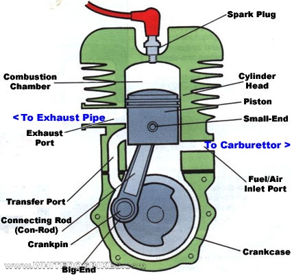
Engine Terminology
Stroke: Either the up or
down movement of the piston from the top to the bottom or
bottom to top of the cylinder (So the piston going from the
bottom of the cylinder to the top would be 1 stroke, from
the top back to the bottom would be another stroke)
Induction: As the piston
travels down the cylinder head, it 'sucks' the fuel/air mixture
into the cylinder. This is known as 'Induction'.
Compression: As the piston
travels up to the top of the cylinder head, it 'compresses'
the fuel/air mixture from the carburetor in the top of the
cylinder head, making the fuel/air mix ready for igniting
by the spark plug. This is known as 'Compression'.
Ignition: When the spark
plug ignites the compressed fuel/air mixture, sometimes referred
to as the power stroke.
Exhaust: As the piston returns
back to the top of the cylinder head after the fuel/air mix
has been ignited, the piston pushes the burnt 'exhaust' gases
out of the cylinder & through the exhaust system.
Transfer Port: The port (or
passageway) in a 2 stroke engine that transfers the fuel/air
mixture from the bottom of the engine to the top of the cylinder
The 2 Stroke Cycle
We have simplified this explanation as much as possible so some of the 'correct' terms have been replaced. There are many more factors which enable an engine to run, such as fuel/air ratios, ignition timing & shaped piston heads (extensively used in 2 stroke engines) but the explanation below outlines the basic differences between 2 & 4 stroke engine operation.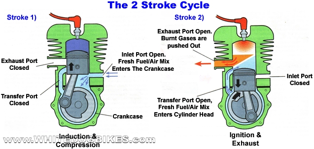
Stroke
|
Piston Direction
|
Actions Occurring during
This Stroke
|
Explanation
|
Stroke 1
|
Piston travels up the cylinder barrel
|
Induction & Compression
|
As the Piston travels up the barrel,
fresh fuel/air mix is sucked into the crankcase (bottom
of the engine) & the fuel/air mix in the cylinder
(top of the engine) is compressed ready for ignition
|
Stroke 2
|
Piston travels down the cylinder
barrel
|
Ignition & Exhaust
|
The spark plug ignites the fuel/air
mix in the cylinder, the resulting explosion pushes
the piston back down to the bottom of the cylinder,
as the piston travels down, the transfer port openings
are exposed & the fresh fuel/air mix is sucked from
the crankcase into the cylinder. As the fresh fuel/air
mix is drawn into the cylinder, it forces the spent
exhaust gases out through the exhaust port.
|
CAR (toyota) wallpapers
 |
toyota prius-c |
 |
toyota prado |
 |
PRADO |
 |
FORTUNE |
 |
FORTUNE |
 |
HILUX TUNDRA |
 |
FORTUNE |
 |
PRADO |
 |
COROLLA |
 |
FJ-CRUISER |
 |
HIGHLANDER |
 |
PRIUS dashboard |
 |
FORTUNER |
 |
PRIUS |
 |
TRUNDA |
 |
PRIUS |
 |
VIGO champ |
 |
VIGO champ dashboard |
 |
vigo champ |
Subscribe to:
Posts (Atom)